Servo Hydraulics
 |
There are three main components of the linear amplifier: the pilot motor (normally a stepper motor however could be a DC motor or AC servo motor); the NC-valve; and the hydraulic cylinder. |
The rotation of the pilot motor is converted into a linear movement of the spool within the NC-valve using the control thread on the control shaft. As the spool moves either the 'tank' or the 'pressure' ports are opened up. The flow of hydraulic medium is controlled into/out of both the piston area and piston ring area.
The closed-loop within the linear amplifier is achieved mechanically via a feedback spindle located within the piston. Located at the NC-valve end of the feedback spindle is a bush. The feedback spindle (which has an opposite thread to the control shaft thread rotates in the same direction to the pilot motor input due to the resulting movement of the piston. This rotation moves the spool to it's neutral position. When in the neutral position the piston will once again be stationary.
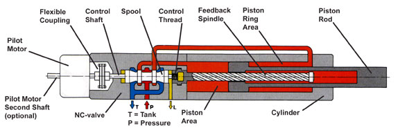
Diagram A) shows the linear amplifier in it's stationary state i.e. the 'pressure' and 'tank' ports are closed. The piston is stationary.
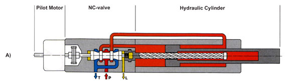
Diagram B) shows the pilot motor rotating a small distance anticlockwise. This causes the control shaft and spool to move in the direction of the motor, causing the flexible coupling to compress. This movement opens up the piston area to the 'Pressure' and the piston ring area opens up to 'Tank'. The piston the extends out of the cylinder. As piston extends the resulting rotation of the feedback spindle (also anticlockwise) results in the spool being moved back to it's neutral position and the piston stops moving.
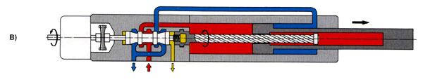
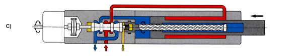
Diagram C) shows the pilot motor rotating a small distance clockwise. This causes the control shaft and spool to move in the direction of the cylinder, causing the flexible coupling to expand. This movement opens up the piston ring area to the 'Pressure' and the piston area opens up to 'Tank'. The piston the retracts into the cylinder. As piston retracts the resulting rotation of the feedback spindle (also clockwise) results in the spool being moved back to it's neutral position and the piston once again is stationary.